What is Islanding?
Islanding is a condition that occurs when a distributed energy resource (DER) such as a grid-tied inverter continues to supply power to a section of the grid that has been disconnected from the main grid. There are two types of islanding: unintentional and intentional. Unintentional islanding occurs when a distributed energy resource (DER) such as a grid-tied inverter shall detect the island, disconnected from the main grid, cease to energize the power system, and trip within 2s. Intentional islanding refers to a situation where a distributed energy resource (DER) such as a grid-tied inverter is intentionally programmed to continue supplying power to an intentional local islands in case of grid outage, either scheduled or unscheduled. Both types of islanding can cause serious safety hazards and equipment damage. Therefore, it is crucial to have reliable and effective islanding detection methods in place to prevent islanding and ensure safe and reliable operation of the electrical grid. Additionally, the DER must be designed and programmed to ensure that it can safely operate in islanded mode without posing any risk to the electrical grid or the public.
According to the IEEE 1547-2003 [1], Distributed Energy Resources (DERs) must be able to detect and shut down unintentional islands within 2 seconds, as islanding was previously considered a safety hazard. However, the updated 2018 version [2] of the standard now permits intentional islanding, as long as the system is designed to accommodate it. While the control and dynamics of an intentional island are not covered by the 1547 standard, the 2018 version sets limits on the impact an intentional island can have on the Area Energy Power System (EPS) and requires DERs to meet specific requirements when operating in an intentional island that includes Area EPS assets.
Importance of Islanding Detection
Without reliable and effective islanding detection methods, unintentional or intentional islanding can pose great risk. A few are given below.
· Safety: Islanding can pose significant safety hazards for utility workers and the public. If a disconnected section of the grid continues to receive power from a DER, it can lead to electrical shock, electrocution, and even fire hazards.
· Equipment damage: Islanding can also cause damage to the equipment in the grid-tied inverter and the electrical grid. Continued power supply to the disconnected section of the grid can cause equipment failure, leading to costly repairs and downtime.
· Grid stability: Islanding can lead to a complete collapse of the electrical grid, causing widespread power outages and disrupting essential services. Islanding detection ensures that the DER system is shut down in a timely manner to prevent any instability in the electrical grid.
· Compliance: Many countries and regions have regulations and standards in place that require islanding detection in DER systems. Compliance with these regulations is essential to ensure that the DER system is safe and reliable.
· Reliability: Islanding detection methods ensure that the DER system is operating correctly and provides reliable power supply to the electrical grid. Timely detection of islanding and shutdown of the DER
Types of Islanding Detection
There are generally two types of islanding detection methods used in grid-tied inverters:
1. Passive methods: These methods use the inherent characteristics of the electrical grid to detect islanding, such as frequency and voltage changes. Passive methods do not require any additional hardware or communication between the inverter and the electrical grid.
2. Active methods: Active islanding detection techniques involve the generation of disturbances in the electrical grid that the inverter system is connected to, and then analysing the output voltage or frequency of the inverter to investigate if there is islanding and if the grid remains stable. Active methods can be more accurate and reliable than passive methods, but they require additional costs and complexity.
Passive Islanding Detection methods
Under/Over Voltage Protection: This method involves monitoring the voltage level of the electrical grid and shutting off the grid-tied inverter if the voltage exceeds or falls below a certain threshold. This is a simple and cost-effective method, but it can lead to false positives if the voltage fluctuations are due to other causes.
Frequency Shift: This method involves monitoring the frequency of the electrical grid and detecting any changes that occur during islanding. If the frequency changes significantly, the grid-tied inverter will be triggered to shut off or move to islanded operation depending on the design on inverter control system. This method is more reliable than voltage protection, but it may not detect islanding in situations where the frequency changes are gradual.
Rate of Change of Frequency (ROCOF) detection: This method measures the rate of change of frequency in the electrical grid and compares it to a predetermined threshold. If the rate of change of frequency exceeds this threshold, the grid-tied inverter will be shut off or move to islanded operation.
Voltage phase Jump Detection: This method monitors the voltage phase angle and detects any sudden jumps that occur during islanding. If a phase jump is detected, it will indicate islanding. This method is simple and cost-effective, but it may not be reliable in situations where the phase angle changes gradually.
Harmonics Detection: This method involves monitoring the harmonics in the electrical grid and detecting any changes that occur during islanding. If the harmonics change significantly, it will indicate islanding.
Active Islanding Detection methods
Active islanding detection methods are designed to apply regular disturbances to the inverter system and analyse the output voltage or frequency to detect islanding and ensure grid stability. Some of the most common active methods include:
Active Frequency Drift: The Active Frequency Drift (AFD) method is an active islanding detection technique that adds a small disturbance current signal to the inverter reference output current. During islanding conditions, this method creates a constant drift in the inverter frequency, which reaches the frequency boundary limits set for islanding detection.
Sliding Mode Frequency Shift (SMS):This method detects islanding by perturbing the voltage phase of the point of common coupling (PCC) with positive feedback and monitoring the frequency deviation. During islanding operation, the phase angle of the load and the frequency vary, and if the frequency deviation exceeds the threshold, islanding is detected.
Impedance measurement: This method detects islanding by changing the amplitude of the output inverter current. During islanding operation, the voltage variation caused by the current perturbation is calculated as dv/di, an equivalent impedance seen from the inverter. If the calculated impedance exceeds the threshold, islanding is detected.
Negative-Sequence Current Injection: This method injects a negative-sequence current to perturb the voltage-sourced converter and monitors the negative-sequence voltage at the PCC to detect islanding. The injected current does not affect the PCC voltage during normal grid-connected operation, but creates a voltage unbalance during islanding, which can be detected if it exceeds the threshold.
Variation of Active and Reactive Power Injection: This method involves injecting a small amount of active or reactive power into the grid and monitoring the output voltage or current of the inverter resulting in either voltage or frequency drifts. These deviations when go above the threshold levels, islanding can be detected.
Islanding detection methods, both passive and active, have their limitations when it comes to detecting all possible islanding conditions. One of the key limitations is the non-detection zone (NDZ), which is defined as the range of frequencies and power imbalances where the islanding detection method fails to operate effectively. The NDZ can occur due to various reasons, such as the sensitivity of the method or the type of load connected to the system.
Passive islanding detection methods, such as the ROCOF method, have a relatively larger NDZ due to their reliance on grid impedance variations. The ROCOF method may not detect islanding events when there is a sudden load change or a voltage disturbance. Similarly, the harmonics-based method may not detect islanding if the harmonic components of the voltage and current waveforms are cancelled out. Active islanding detection methods may have a smaller NDZ but can affect the system’s power quality and stability. Additionally, some active methods may not be effective in detecting islanding in systems with a large number of inverters. Therefore, it is crucial to carefully choose the appropriate islanding detection method based on the system’s characteristics and requirements
An active islanding detection method with zero NDZ
As a part of our research work on microgrids under the Energy Consortium, IIT Madras, an active islanding detection method with zero non detection zone was developed (patent pending, Patent No. 201841030076, Filed 2019-08-07) [4].
For the grid connected operation of the inverter, we have considered dqreference frame control. The dq reference frame control is a well-established method that is widely used in power electronics applications. This technique transforms the three-phase AC quantities like voltage and current into two DC quantities, which simplifies the control strategy.
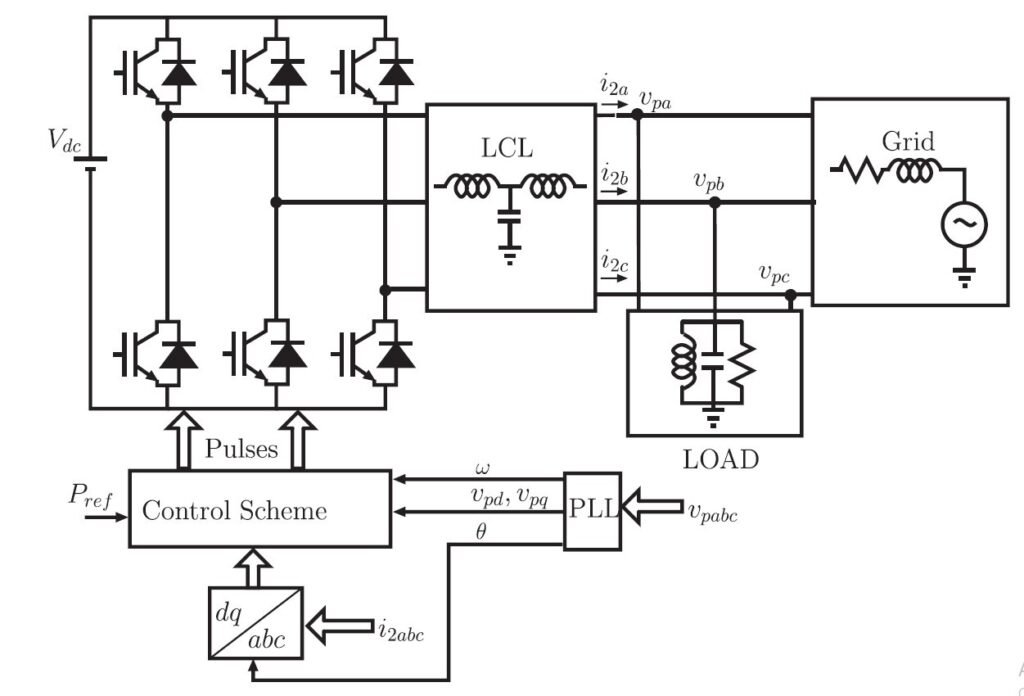
Figure 1: Block diagram of grid connected inverter (Source: 10.1109/TIE.2019.2931231)
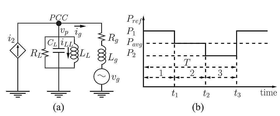
Figure 2: (a) Single phase equivalent circuit of grid connected inverter (b) Power injection pattern (Source: 10.1109/TIE.2019.2931231)
Figure 1 shows the block diagram representation of a grid connected inverter and Figure 2(a) shows its equivalent circuit. In the developed Islanding Detection method, a periodic pattern of step changes in the active power reference is introduced is shown in Fig. 2(b). The ratio between the d-axis component of the voltage at the PCC (vpd) and the d-axis current injected into the PCC (i2d) is continuously monitored. This ratio in grid connected mode of operation (M) can be found to be dependant on i2d whereas in islanded mode, the ratio remains a constant and depends only on connected load.
M is calculated for 3 different power injection values (M1, M2, and M3) and the differences are calculated as d1 = M2 – M1 and d2 = M3 – M2. Since the value of M is power independent in islanded mode, the value of d1 » d2 » 0. Hence, ID is implemented by checking whether d1 and d2 fall below a threshold value (Δth). This algorithm is summarised in the flow chart given in Fig. 3.

Figure 3: Flow chart of the Islanding Detection algorithm (Source: 10.1109/TIE.2019.2931231)
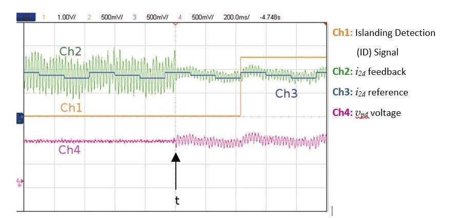
Hardware results of the above algorithm tested on a 2kW experimental setup is shown in Fig. 4. At time t, islanding occurs. After the occurrence of islanding, the voltage at the point of common coupling (PCC) follows a specific pattern depicted in Ch 4 in Fig. 4. The controller calculates the average value of M for each interval and compares them at the end of each cycle of the reference pattern. When d1 and d2 fulfil the ID criterion, a GPIO pin is activated to indicate the presence of islanding as shown in Ch 1 in Fig. 4.

Figure 4: Experimental results of Islanding Detection algorithm (Source: 10.1109/TIE.2019.2931231)
This detection method is not affected by voltage fluctuations or frequency changes that commonly occur in weak or stiff grids, making it suitable for both types of grids. The step increment or decrement is intentionally kept small to avoid exceeding voltage limits. Unlike signal injection-based methods, this method does not extract specific frequency components or require spectrum analysis or filtering. Instead, it monitors the ratio of d-axis component of voltage at PCC and d-axis current injected into PCC. Additionally, the power variation pattern is designed to maintain the required average value, and it does not create any significant harmonic content in the current. For further information, please refer to the publication [3] and patent [4] associated with this work.
The Energy Consortium at IIT Madras, under the direction of Prof. Krishna Vasudevan, conducts active research in the field of microgrids. The research focuses on decentralized control of distributed energy resources, integration of energy storage systems, control of power quality through harmonic elimination, and protection schemes. To learn more about the research, it is recommended to read the latest publications (https://ieeexplore.ieee.org/author/37293260600)
Author – Amrutha Haridas, Project Officer, IGCS Research Programme on Sustainable Power Engineering – Phase II, Dept. of Electrical Engineering, Indian Institute of Technology, Madras
References
[1] “IEEE Standard for Interconnecting Distributed Resources with Electric Power Systems,” in IEEE Std 1547-2003 , vol., no., pp.1-28, 28 July 2003, doi: 10.1109/IEEESTD.2003.94285.
[2] “IEEE Standard for Interconnection and Interoperability of Distributed Energy Resources with Associated Electric Power Systems Interfaces,” in IEEE Std 1547-2018 (Revision of IEEE Std 1547-2003) , vol., no., pp.1-138, 6 April 2018, doi: 10.1109/IEEESTD.2018.8332112.
[3] D. Sivadas and K. Vasudevan, “An Active Islanding Detection Strategy With Zero Nondetection Zone for Operation in Single and Multiple Inverter Mode Using GPS Synchronized Pattern,” in IEEE Transactions on Industrial Electronics, vol. 67, no. 7, pp. 5554-5564, July 2020, doi: 10.1109/TIE.2019.2931231.
[4] Sivadas Deepthi and Vasudevan Krishna, “AN ACTIVE METHOD OF ISLANDING DETECTION”. Indian Patent Application No. 201841030076, Filed 2019-08-07 Published 2020- 02-13