Motivation:
The world is shifting toward the gas-based fuel economy from the conventional liquid-based fuel economy to envision the carbon net zero economy model. The prime advantages of this shift include low gas emission, lower economic value, and utilization of existing vehicle engines after little modification. Natural gas has been utilized in many countries after the advancement achieved in the exploration of shale gas. Now, natural gas has become an essential energy resource, and it is predicted by British Petroleum (BP) that the natural gas demand will grow at an average rate of 2.4 percent annually until 2030. To satisfy the sharp rise in worldwide natural gas demand, natural gas needs to be transported from exploration sites to potential markets. Liquefied natural gas (LNG) and pipeline natural gas are the only successfully commercialized technologies to transfer the gas up longer distances. Out of them, pipeline natural gas became uneconomical for longer distances, providing the rise to develop the LNG based natural gas movement. In today’s world, a more significant amount of natural gas is transported in the liquefied form for longer distances. Apart from the large-scale transportation of natural gas, small-scale transportation needs are fulfilled by the compressed natural gas (CNG) form. However, CNG is not an attractive option to be used for natural gas due to two primary reasons. CNG requires very high gas pressure for the storage and transportation of natural gas, which has higher safety concerns and requires larger storage space. Another issue with the CNG is regarding the volumetric energy density of the fuel. LNG is stored as a cryogenic liquid with an energy density equivalent to diesel fuel and less space requirement with the comparison of CNG.
What is the most efficient, safe, and economical alternative to CNG?
The world is looking toward natural gas hydrate (NGH) technology to utilize it for the storage and transportation of natural gas. According to many published case studies in renowned journals, NGH technology requires less capital investment than CNG technology for small to medium scale transportation. At the same, the payback period (time required to recover the capital investment) is much higher in the case of CNG, more than the LNG technology for the same conditions. Due to all these prominent reasons, NGH has been emerging as a sustainable approach for natural gas transportation under the research and development stage.
What is gas hydrate technology?
When high pressure gas is encapsulated in the water cages made out of hydrogen bonding among the water molecules and solidified at low temperature, the gas hydrate is formed. The majority of the gases form gas hydrates with water molecules, including natural gas. The gas hydrate forms in the presence of natural gas is known as natural gas hydrate. Sir Humphrey Davy was the pioneer who synthesized the gas hydrate from chlorine gas, known as oxymuriatic gas and water, in 1811. Significant research in the field of gas hydrates was started by troubleshooting the issue of natural gas blockage in the gas transportation pipeline in 1934. In the current world, gas hydrate research spread in the areas like natural gas exploration of in-situ natural gas hydrate, natural gas storage, separation of gases, carbon dioxide capture and sequestration, water desalination, etc.

Fig.1 Types of different gas hydrate structures
(Source:https://doi.org/10.1051/epjconf/201714302106)
The gas hydrate structure depends upon the member gas molecule or the compound which can form the gas hydrate with the water molecules. The detailed schematic diagram of various gas hydrate structures is shown inFig 1. SI structure has 46 water molecules in the sequence of two small 512 cages with six large 51264 cages. It can accommodate mainly methane, ethane, and carbon dioxide, like gas molecules. While structure SII has 136 water molecules, forming 16 small 512 cages with twelve large 51264 cages to form captured hydrogen, nitrogen, and oxygen kind molecules in small cages and tetrahydrofuran and propane like molecules in the large cage. Additionally, structure H can also form which can 136 water molecules in the configuration of three small 512 cages, two medium 435663 cages, and one large 51268 cages.
Translation of gas hydrate technology to natural gas storage:
First demonstration of natural gas storage in the form of NGH: Mitsui Engineering & Shipbuilding Co., Ltd (MES) from Japan has been making efforts to study and develop the supply chain for the NGH since the late 20th century. MES started the conceptual planning to make NGH pellets to easily transport them from one place to another.
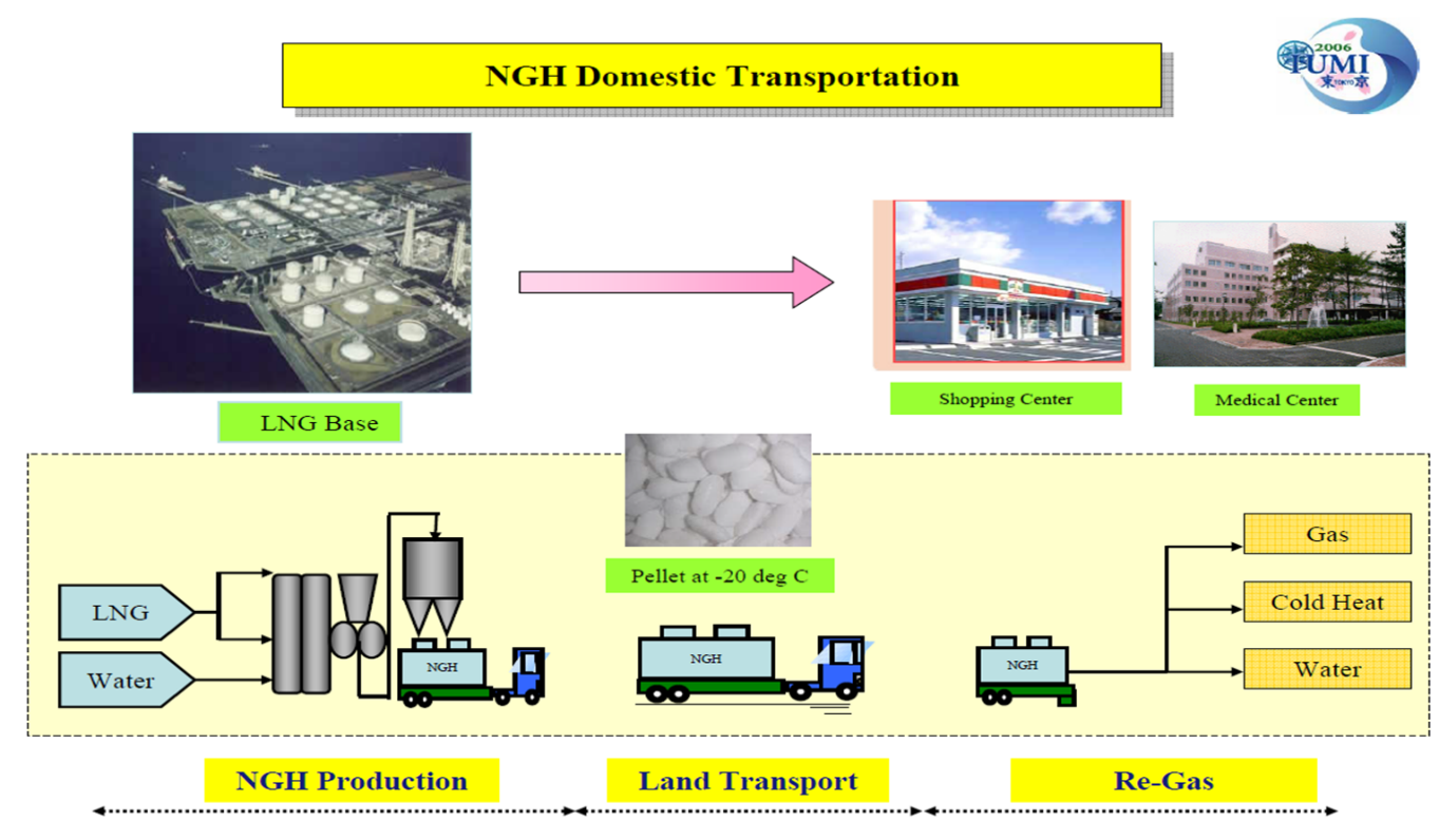
Fig.2 Concept of NGH domestic land transportation between the production site and consumers
(Source:https://iumi.com/images/stories/IUMI/Pictures/Conferences/Tokyo2006/Tuesday/10.energy.takaoki.pdf)
According to data published in 2007, MES and Mitsui developed the manufacturing facility for domestic NGH transport on land, which was used to transport the NGH pellets from the LNG base to the customers. The project got assistance from Japan Oil, Gas, and Metals National Corporation (JOGMEC). This project got further assistance from another 6 industries in Japan. As shown in Fig. 2, the LNG is directly used to produce NGH in the presence of water. The next step involves the land transportation of NGH at -20° C temperature to the customer, where it regasifies and is used for various applications. The regasification of NGH pellets gave cold heat apart from the water and natural gas, which can be utilized for various cooling purposes.
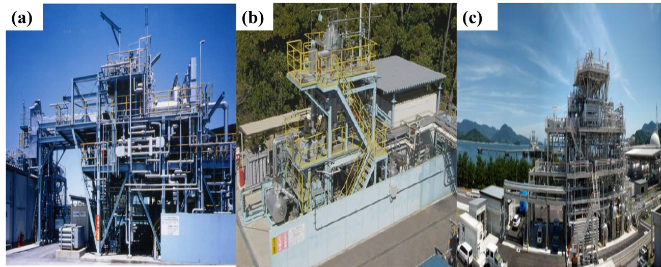
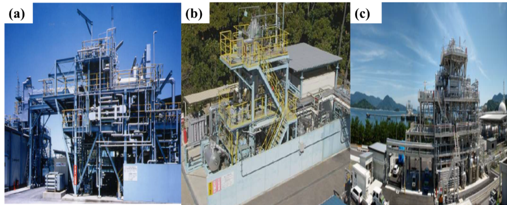
Fig.3 (a) First NGH plant (Process Development Unit) at MES Chiba works (b) Bench Scale Unit plant at MES Chiba works (c) NGH production plant at Yanai LNG based power station
(Source:https://iumi.com/images/stories/IUMI/Pictures/Conferences/Tokyo2006/Tuesday/10.energy.takaoki.pdf)
The commercial production facility was developed in order to cater to the supply chain of NGH transport on the land. The process of developing a plant for 600 kg/day NGH production capacity at MES Chiba works, Chiba, is shown inFig.3. provides a photo of the NGH production plant with gigantic 5 tons per day capacity at the Yanai LNG-based power station. The current developed Japanese facilities and supply chain management of NGH pellets will be replicated in the whole world in the near future.
In this direction, efforts have been made by the team of researchers from the Gas Hydrates research group at IIT-Madras where a detailed study was conducted on methane gas hydrates and the proposed scale-up model for the continuous production of the gas hydrates. The process flow diagram (PFD) inFig. 4 demonstrates the natural gas hydrate supply chain consisting of the continuous production of natural gas hydrate pellets by using the twin crystallizers coupled with the pelletizer unit extending to the storage and transportation units. A centralized redistribution gas management system is also proposed to minimize production costs. As evident from Fig. 4, this study provides a perfect platform as the formation and handling of the natural gas hydrates required lesser gradients when compared to the methane gas hydrates. This innovative design may help to build sustainable foundation in order to build NGH supply chain worldwide.
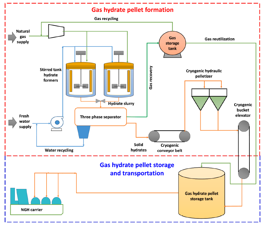
Fig.4 The conceptualized process flow diagram of the natural gas hydrates with two distinct sections considering the palletization of the gas hydrates, followed by the storage and transportation.
Visit the latest publication link attached here for more insightful details. (https://doi.org/10.1016/j.enconman.2022.116044)
Author – Bhavikkumar Mahant, PMRF Ph.D. Scholar, Gas Hydrate Research Group, Department of Chemical Engineering, Indian Institute of Technology Madras